Assembly Guide
Video
Preparation
Before starting assembly, make sure you have:
- All necessary parts (refer to Bill of Materials)
- Required tools (diagonal pliers, M2 screwdriver)
- A clean work surface
Assembly Steps
1. Material Preparation
- Check that all 3D printed parts are complete
- Clean support material from printed parts
- Ensure all holes are clear
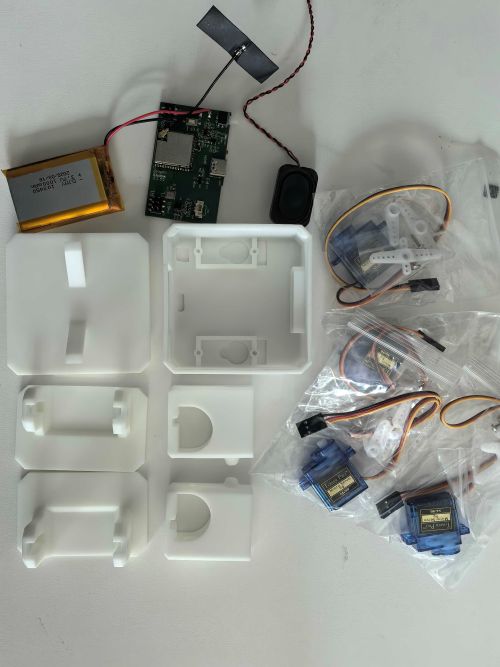
Figure 1: All materials prepared
2. Electronic Component Installation
- Install servos (Double row 3-pin on both sides -> outer side connects brown servo wire (negative pole), upper leg lower foot connection method)
- Connect speaker
- Connect battery
- Flash firmware
- Turn on switch (initialize servos to initial position -> 90 degrees ensure servo gears don't change during installation, arms initially at 45 degrees downward)
- Remove servo wires, wait for body installation to complete before reconnecting
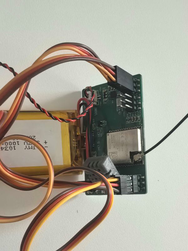
Figure 2: Electronic component installation
3. Leg Assembly
Use the two large screws included with the servo to secure it
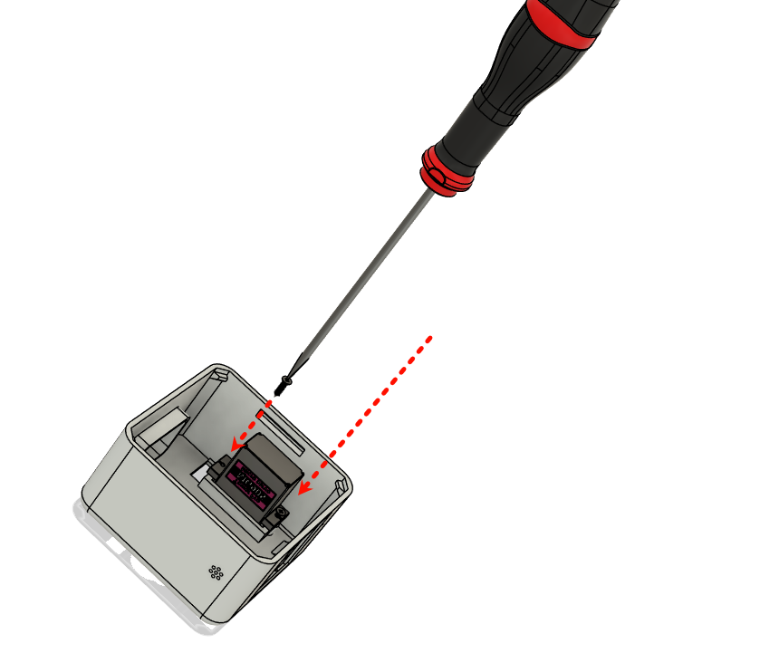
Figure 3: Assemble leg servo
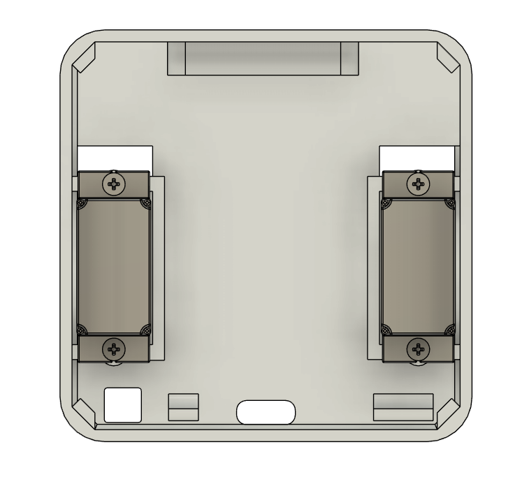
Figure 4: Complete leg servo assembly
Trim servo cross arm: cut the two longer ends by approximately half
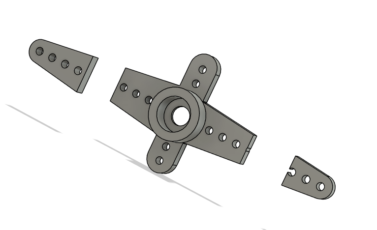
Figure 5: Trim servo cross arm
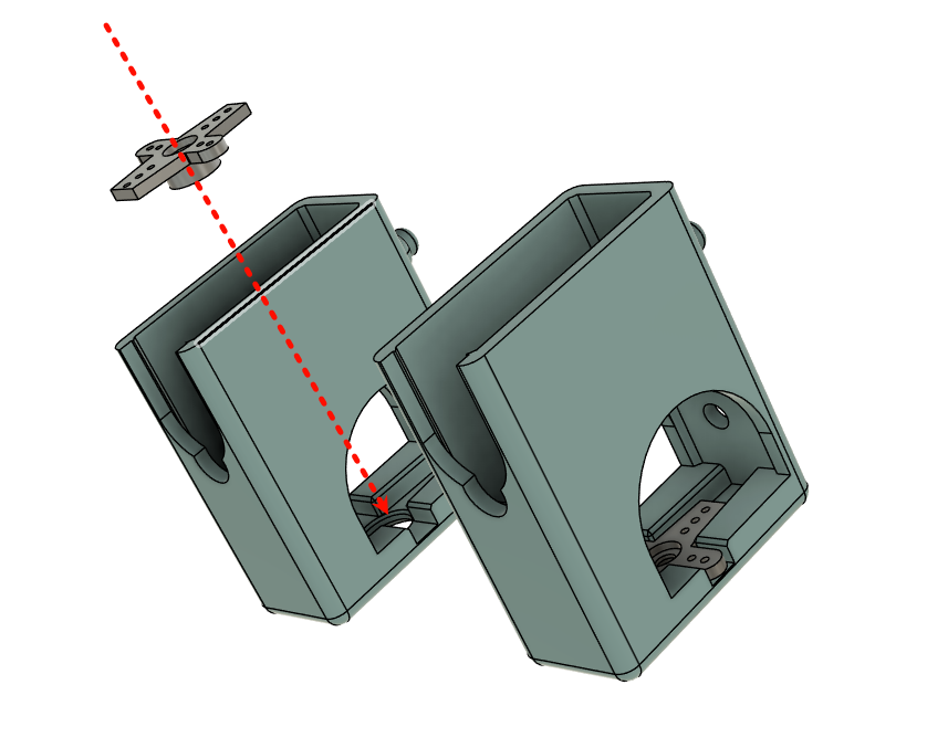
Figure 6: Install cross arm to leg
Keep leg cylindrical protrusion facing the screen side, leg direction vertically forward (try to avoid pigeon-toed or duck-footed, some may have a slight angle which doesn't affect performance)
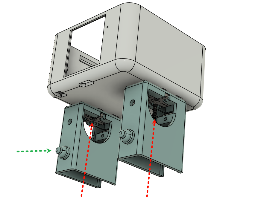
Figure 7: Secure leg and tighten fixing screws
4. Foot Assembly
Use the shaped arm shown below, install vertically upward, and tighten screws
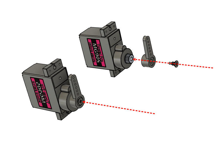
Figure 8: Secure foot servo arm
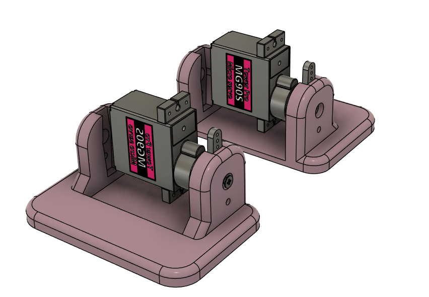
Figure 9: Secure foot
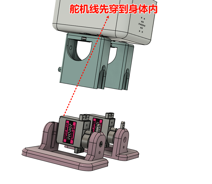
Figure 10: Route foot servo wire through body
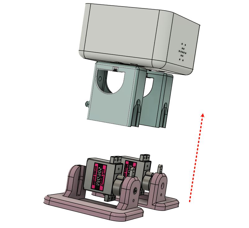
Figure 11: Foot installation
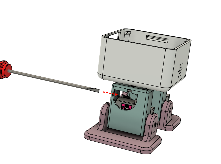
Figure 12: Install foot servo fixing screws
5. Circuit Board Installation
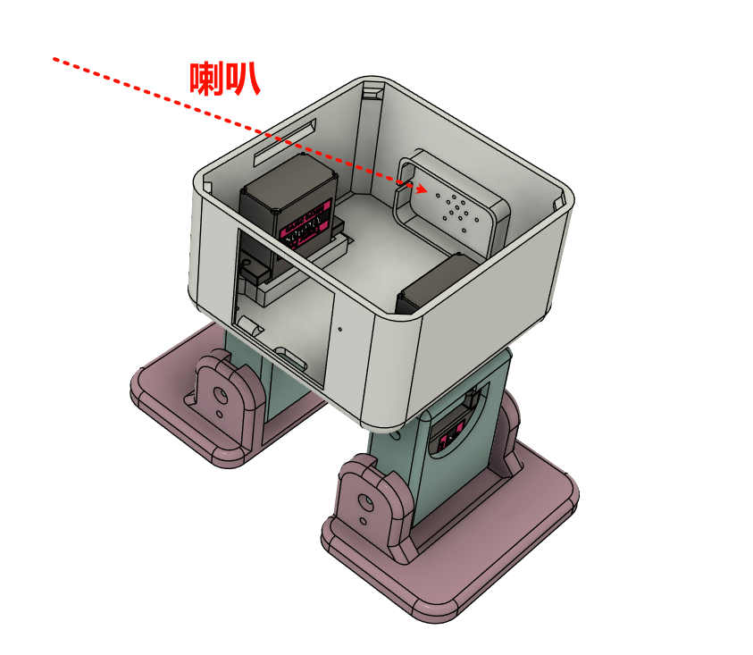
Figure 13: Secure speaker, there's a slot with wire
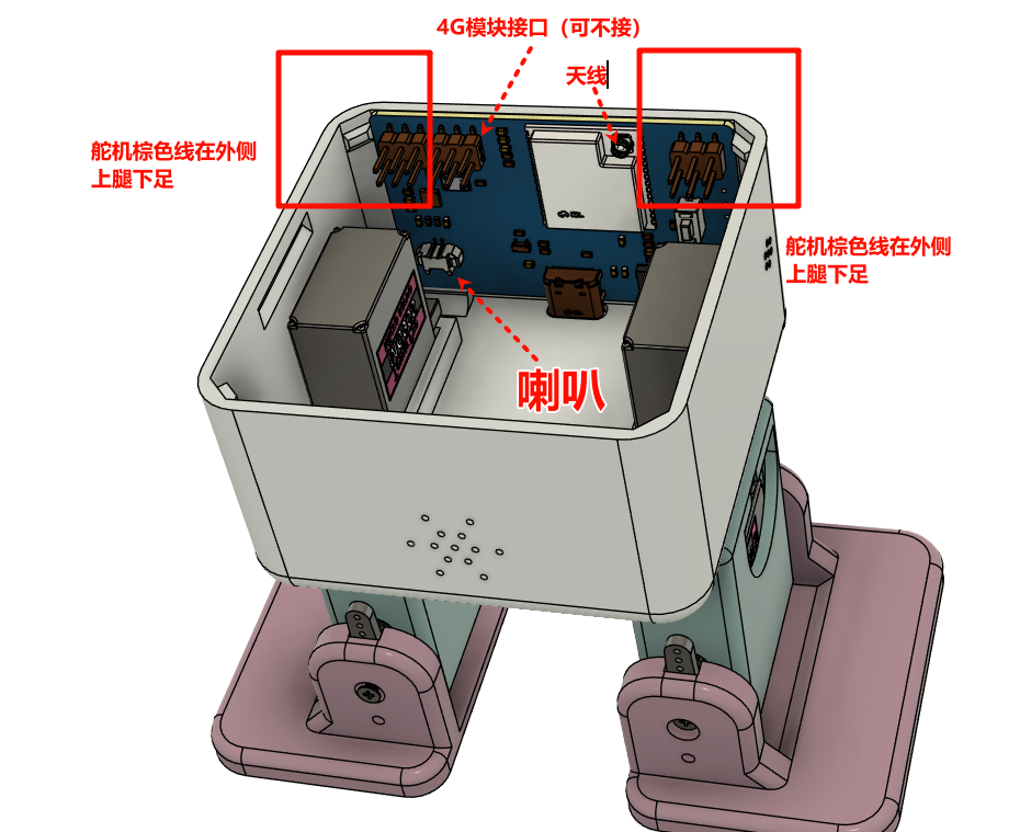
Figure 14: Install servo wires, speaker, battery, antenna
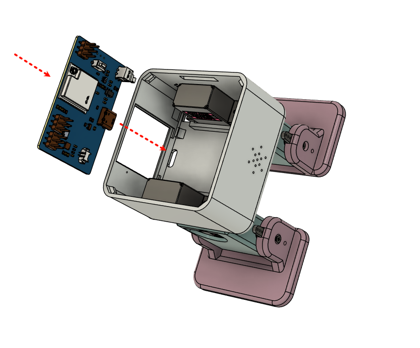
Figure 15: Install main board
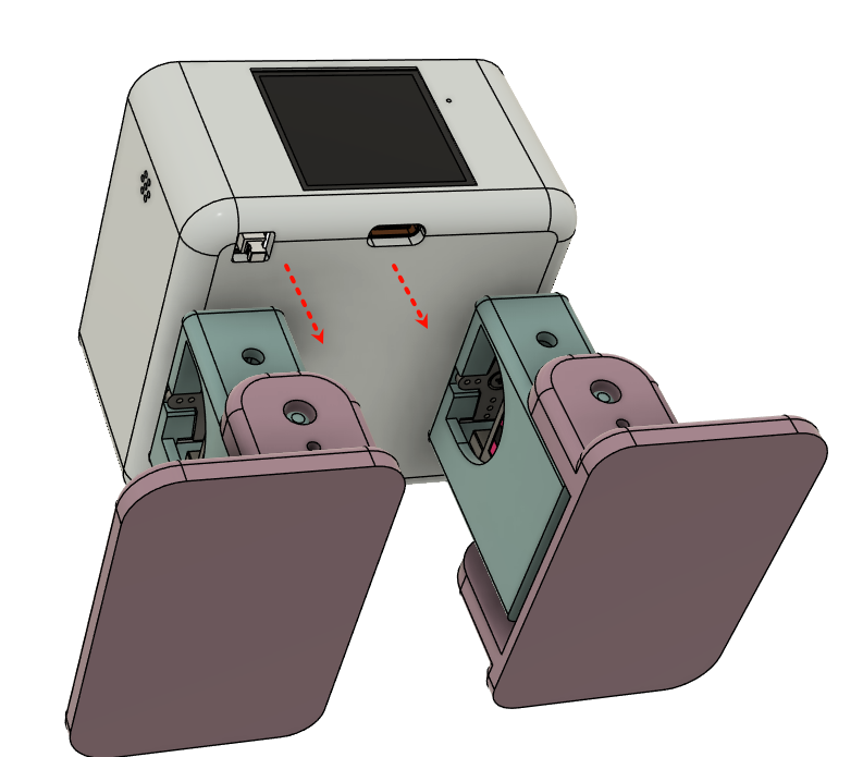
Figure 16: Ensure screen, Type-C charging port and switch are properly installed
6. Head Cover Installation
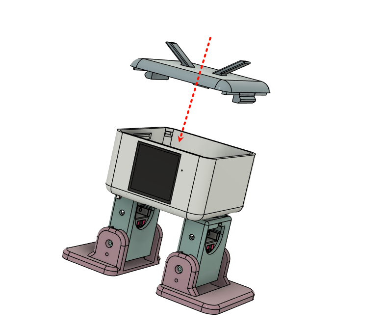
Figure 17: Head cover front side has a protrusion to press down circuit board
Precautions
- Handle carefully during assembly to avoid damaging parts
- Ensure all screws are tight but don't over-tighten
- Pay attention to servo installation direction
Common Issues
-
Servo not moving
- Restart
- Check if wiring is correct
- Confirm power supply is normal
- Verify firmware is flashed correctly
-
Unstable structure
- Check if screws are tightened
- Confirm 3D printed parts are not deformed
Next Steps
After completing assembly, refer to the User Manual page to learn how to start using your robot.
If you encounter any problems, please check our FAQ or contact technical support.